ENPH 259: Servo Motor RPM Control
This project was a part of the UBC ENPH 259 Experimental Techniques course. In this project, my lab partner and I constructed a circuit that could manually control the RPM of a motor, from scratch. Building on top of previous projects, we worked on other topics such as feedback control in circuits, timing diagrams, circuit maintenance and digital-to-analog conversion. We hope to build upon these concepts in ENPH 253, where we will be constructing autonomous robots.
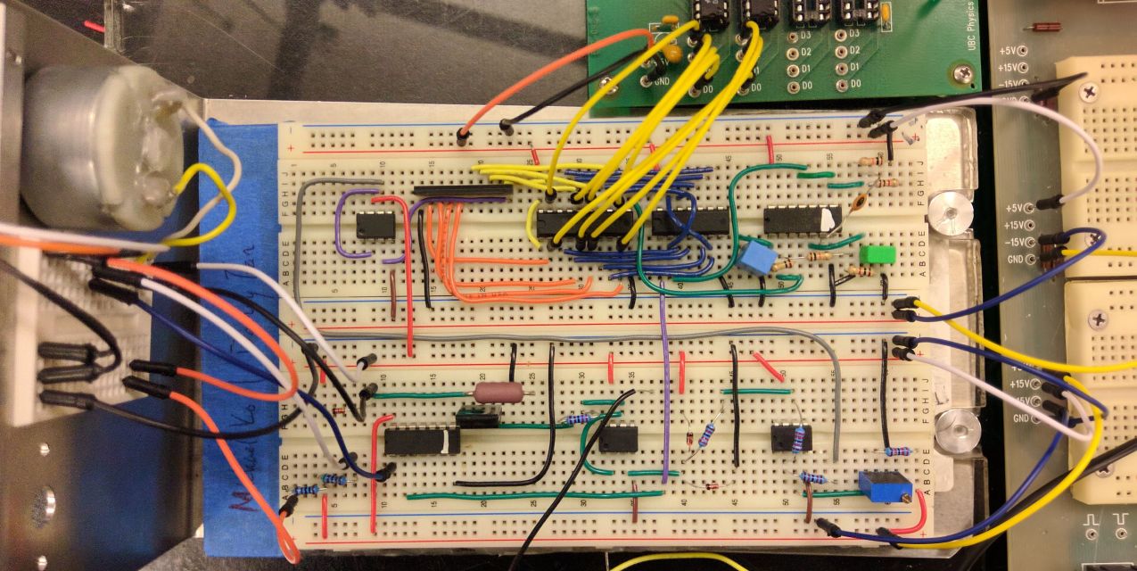
The completed circuit
The cicruit
A Brief Outline:
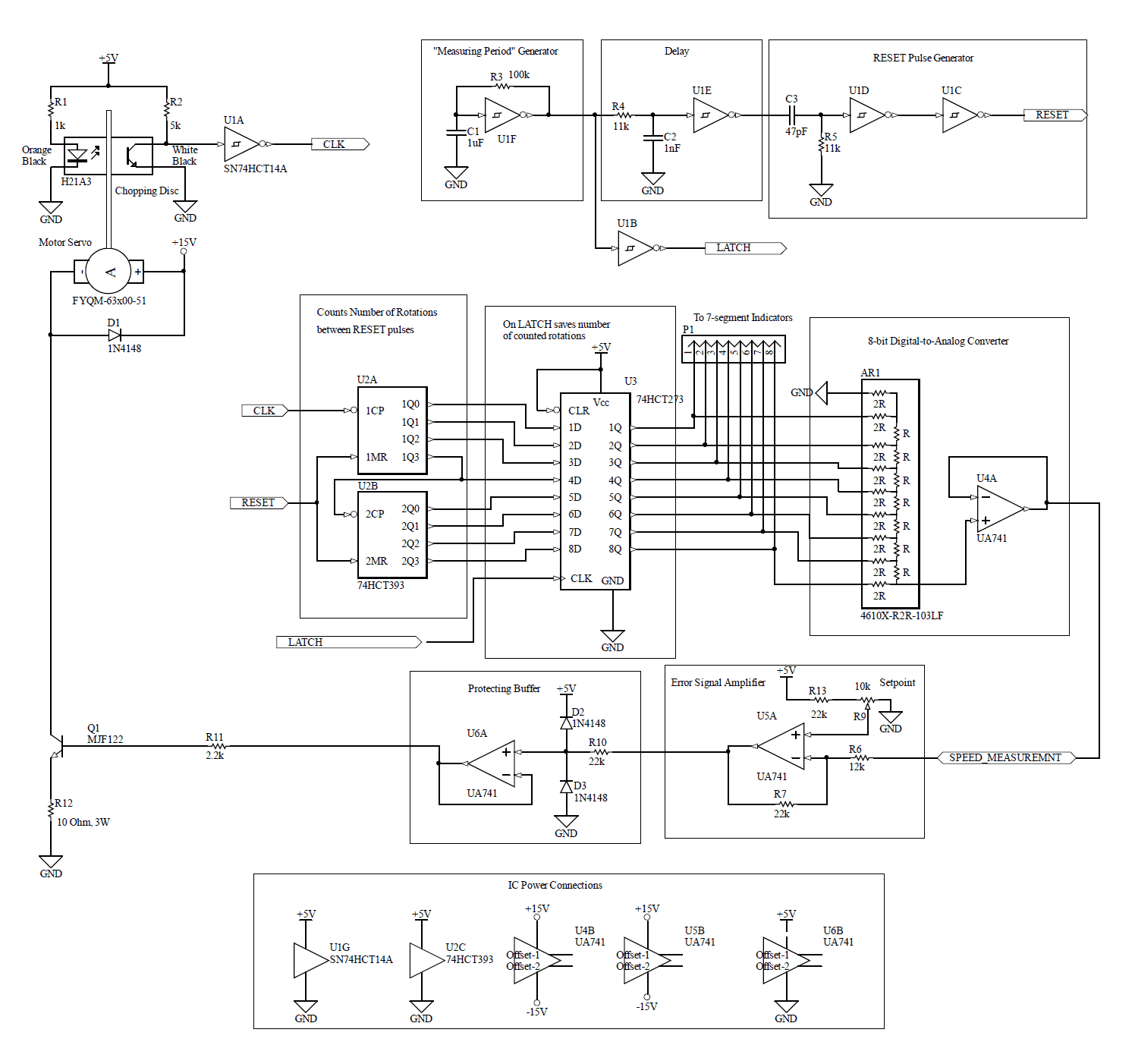
To be able to control the RPM of the servo motor, we needed to find some way to measure the period of the motor and then make adjustments accordingly. The motor rotates a disc containing a preset number of holes. Monitoring this disc is a photo-transistor with an LED directed to it. When a slit on the disc passes over the photo-transistor photons pass through the slit and cause the photo-transistor to conduct and therefore pass a pulse (a CLOCK).
We started off by constructing a sub-component of the overall circuit that enables us to output a pre-determined pulse following a RESET pulse. We want to be able to find the number of times that the photo-transistor is conducted in a certain time interval. Do to this, we use a 16-bit counter and a D-Latch (digital memory). Counting is activated by this pulse generator and eventually reset by the RESET pulse. A small delay is added to the RESET pulse to allow the D-Latch to acquire the state of the counter before it resets. There is a portion of a circuit that allows this to be set towards seven-segment displays for diagnostic purposes (and for awe).
Digital to analog conversion is performed by a resistor ladder, which is read by an "Error Signal" amplifier. The non-inverting input contains a potentiometer which is our manual control for the servo RPM. This "Error Signal" amplifier is actually a difference amplifier, and the difference between the inverting and non-inverting is amplified to the protecting buffer, which protects the servo from large voltages (using diodes). This output is then sent to the BJT, and when switched to on, conducts a current across it to ground, which switches on the servo.
This BJT also serves as the "RPM control" because the current that is permitted to flow to ground by the BJT affects the power supplied to the servo, which controls the RPM. The disc rotates, causing the photo-transistor to pulse, and the cycle starts again.
This post serves mostly to document the project I have done. The previous outline in no way serves as comprehensive description of our work. My final lab report was 16-pages long, outlining many calculations, photos, and uncertainty analysis (all hail the calculus method). It is also just a summary to give some future ENPH 259 people a glimpse of what is done in the course, but not the answers.