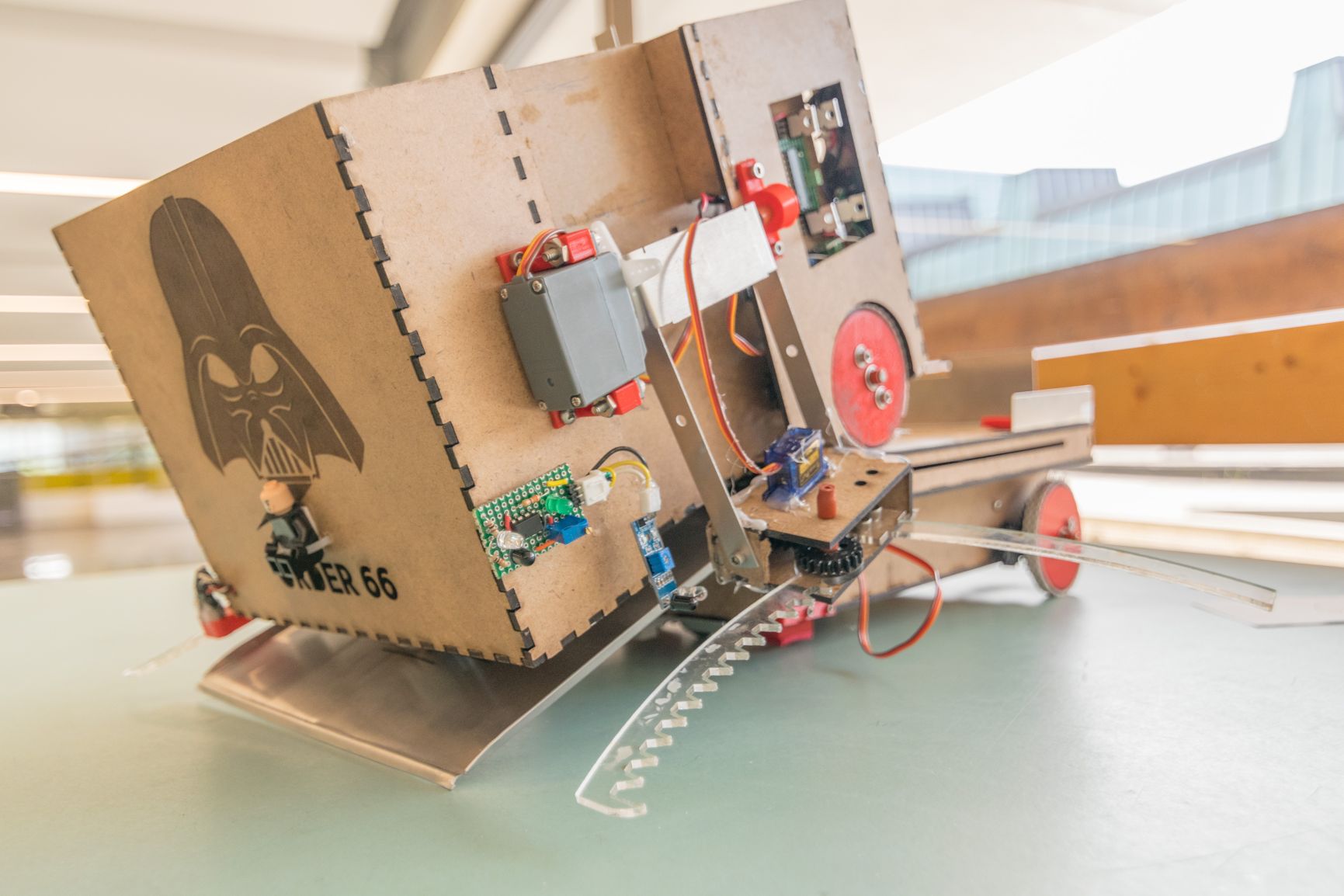
Order 66: A Fully Autonomous Robot
...or two robots, I should say. As part of the ENPH 253 Introduction to Instrument Design course, our main objective is to develop many prototyping skills to develop an autonomous robot that could compete in a competition. We spent roughly three months brainstorming, designing, prototyping, and testing over the summer of 2018 to bring you our glorious little bot.
To see our finished robot in full detail and in action, visit https://order66bot.github.io.
The Competition
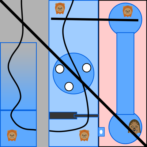
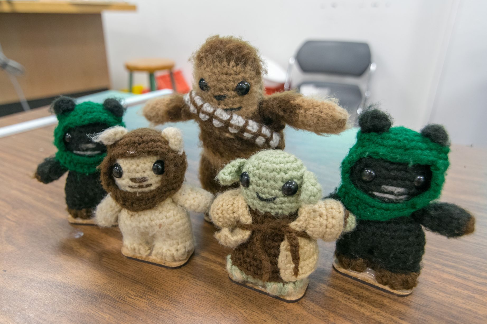
Below this paragraph is a picture of the competition surface. The bot starts at the upper-left hand corner, and encounters some notable obstacles such as a six-inch gap, a gate with an IR blaster that tells us when it is safe to pass (and a rotating table if the alarm is triggered), a zip-line, another six-inch gap with a two-inch incline, a narrow suspending bridge, and lastly another zip-line that brings the robot back to the start. Most of these are connected with black tape that could help us navigate the surface. With the theme of Star Wars, cute Ewok plushies are scattered across the surface, with Chewbacca at the farthest corner. Our robot must rescue them! A robot can earn points by picking up an Ewok (1 point) and returning it back to the starting location (3 points). Chewbacca is harder to save, so the bot is awarded 6 points for his return.
Seems fairly straight forward right? All we need to do is just build a moving piece of machinery, that when the START button is pressed, can waltz its way through the surface, pick up the plushies, and then go back to the start. It is a simple idea, but a difficult one to accomplish. Our program director Andre Marziali mentioned it was going to be one of the toughest challenges in the history of the course, and we wholeheartedly agreed.
Strategy and Initial Design
With a big challenge ahead of us, we decided to narrow the scope by first attempting to retrieve the first three Ewoks, and if there was enough time, go for the rest. The second gap was concerning during the early stages of our design. By reserving the chance to attempt for the remaining two plushies, we needed to account for the second height gap. Early on we had little faith in the strength and stability of a ramp made from sheet metal, and coupled with the idea of an extravagant robot composed of two smaller pieces, we decided to develop two robots.
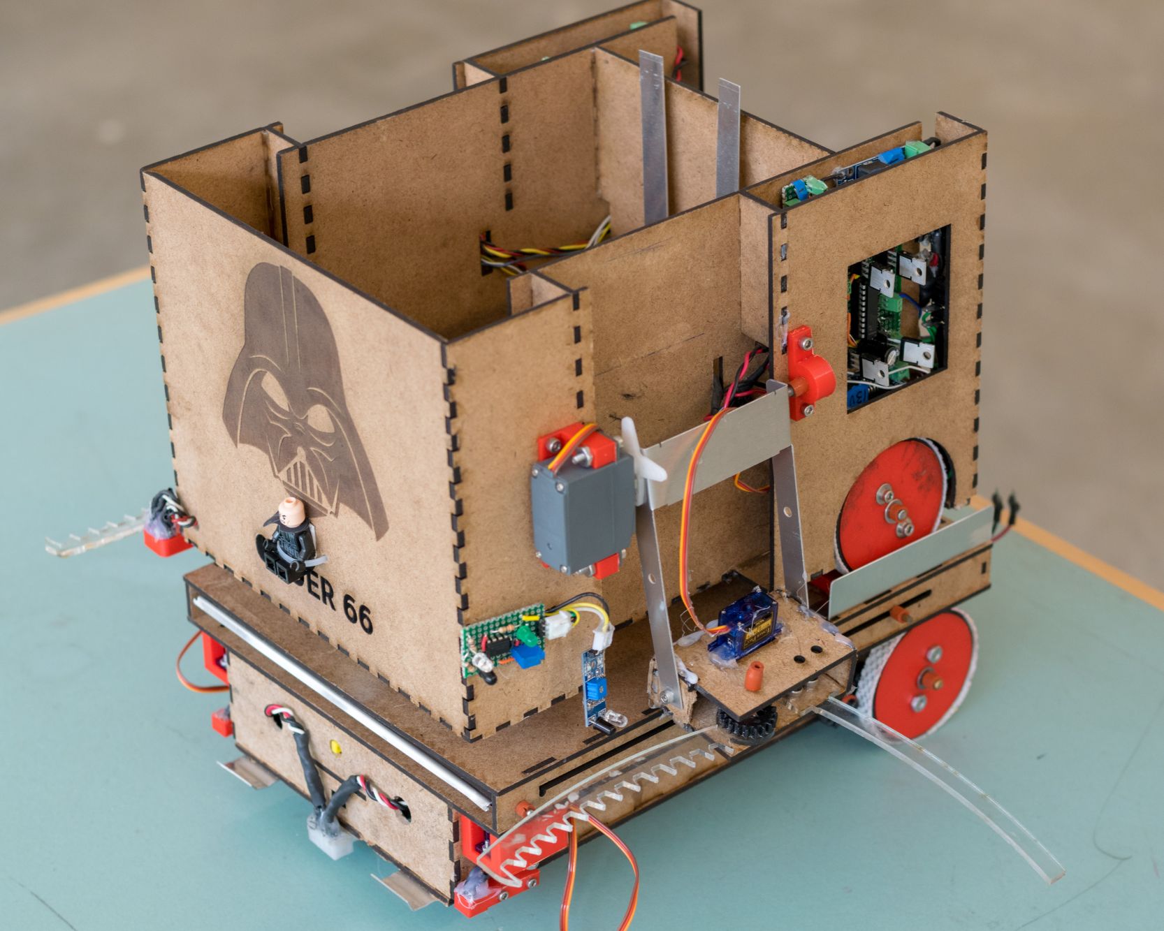
Skipping over much debate and discussion, we would have a "big bot" that served as a large platform and a "small bot" that was responsible for navigation and plushie retrieval. The names are a bit of a misnomer since "big bot" is smaller than "small bot" volume-wise, but that's a discussion for a later time.
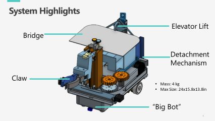
Above is a slide from our design proposal and a 3D model of our robot. If it looks like an abomination to you, I completely agree. There were many issues with our design we didn't recognize having not the opportunity to prototype it yet, but nonetheless it contained everything to address some of the major challenges:
- To retrieve a plushie, the large claw at the front of the robot is attached to a housing that moves up and down a rack and pinion. This is how we envisioned we would deal with the gap and having our bot accommodate for two distinct height levels. The rack and pinion was mounted on the top of a Lazy Susan, which is further connected to a set of gears, giving our claw swivel support such that it could retrieve bots at any angle.
- To cross the gap, we have our "bridge", which is a flat piece of sheet metal, attached to the top of the rack and pinion system. The idea was that the claw would retrieve the first Ewok before the gap, rotate the rack and pinion 180 degrees, literally drop the bridge, and release the Ewok into our basket.
- The second gap could then be overcome with "big bot", which contains inside it a platform that would extend, serving as the second bridge. Due to power limitations and rules, we must power off "big bot" when using it as a bridge, so we have wires in the rear of "small bot" that would physically disconnect when the time came.
- Once we had retrieve the plushies we needed, either at the end of the surface or before the second large gap, we would use an elevator lift to raise the basket. The basket would then hook on to the zipline, carrying the plushies back to the start.
- Navigating the course is done by using QRD light sensors and IR sensors. We could have used encoders, but we felt like it was more "hardcoding" then autonomy.
Checks off all the boxes right? It wasn't until when we got our hands dirty that we discover that our design needed some major changes.
Electrical Design
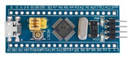
My job for the majority of the competition was the electronic backbone. From stripping wire to motor controls, I led the design of most of our electronics. One of the major design choices we made early on was which microcontroller we would use. The new contender was a small bare-bones board dubbed the "Blue Pill" (STM32F103C) that was slightly more powerful than the existing all-in-one platform custom designed for this course called the TINAH. The TINAH had all the bells and whistles soldered to the board: potentiometers, LCD screen, MOSFET drivers, protection circuits, and more. The major appeal with the Blue Pill was its faster CPU, smaller footprint, and cheap price. This mean that we would be able pick and chose the components we want to use, make our PID loops faster, and easily replace any Blue Pills that we eventually fry. Eager for the challenge, we decided to embrace the new platform, fully knowing we would have little support from our instructors (they were investigating this platform to replace the old TINAH).
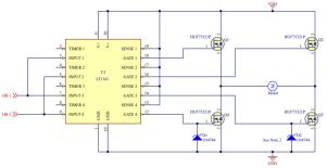
Since our Blue Pill lacked any MOSFET drivers, we need to build our own H-Bridge circuit that would be able to switch on our motors in positive or negative polarity, so that it can drive forwards or backwards. Luckily, our lab director provided us with the Linear Technology LT1161 Quad-Protected High-Side MOSFET Driver that was capable of switching 4 MOSFETs. MOSFETs are like electrical switches; we used them to control whether or not a motor is on, and in which direction.
A basic schematic of the H-Bridge circuit is shown. We made some further adjustments down the road to alleviate some issues such as sudden changes in voltage and the potential for the short circuiting to fry our Blue Pill pins. This involved a higher capacitance decoupling capacitors and some protection techniques here.
Full schematic here. The actual designed H-Bridge PCB below was done to achieve these goals:
- High voltage at the top, low voltage/ground at the bottom
- Easy replacements for the gate driver or the MOSFET themselves should they fry
- Easy swapping of H-Bridge circuits using screw terminals
- Other physical design constraints such as orientation and size.
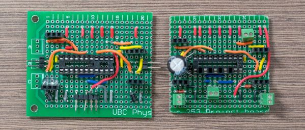
The above image shows an early prototype of the H-Bridge circuit on the left and a near final design on the right. Hopefully the changes above are evident here. Some other circuits/components that I designed:
- A PCB for power distribution. It would take inputs from our large 16V Li-Po battery and power our motors, and a smaller 9V battery to power our sensors and microcontroller. It was important for us to isolate motor noise from the microcontroller and sensors as much as possible.
- An LED object detector (we ran out of ones on hand and Amazon was too expensive).
- A board to handle our IR beacon detector. We decided to make the use of many IR sensors to make our readings more accurate.
- The IR beacon output 10kHz and 1kHz signals to identify when it was safe, and using analog filtering, we could detect both. The IR detector circuit was provided by our instructors. We made some modifications to amplify the signal many times and to process both frequencies. Filtering weakened the signal and having access to both frequencies allowed us to guarantee the beacon was actually outputting the proper signal.
Lastly, a major electrical consideration was controlling both "big bot" and "small bot" while powering off "big bot" when necessary. The solution here was to make the use of two microcontrollers and in software coordinate the states. Due to the lack of pins, we simply used digital signals rather than SPI/I2C to tell "big bot" to advance to the next state. For example, when "small bot" gets a sufficiently high reading for the IR sensor, it will tell "big bot" to advance to the next state, in which it will stop. The power-off sequence was done by physically detaching the power and ground rails when we needed to detach as mentioned before.
Prototyping Changes
As we developed our robot and tested some of the components, it became obvious to us that certain changes needed to be made to make our robot perform better, especially for time-trials that composed a large portion of our grade. It was here that our robot's design was much more "natural" to the design of the competition. The most significant of these changes was our claw design.
We first realized that the size of the sheet metal that served the bridge needed to be much larger due to how the robot approached to the gap at an angle. This increased its weight and therefore it was no longer feasible to use the original system to drop the bridge. In addition, the 3D-printed plastic housing for the front claw and motors, while we obtained a functionally working version, was incredibly heavy and encountered excessive friction as it rode up and down the rack. As the claw moved to the top of the rack, the center of mass of the system moved vertically significantly such that the Lazy Susan became somewhat unstable and we were not confident that the hardboard chassis could sustain the weight, especially when factoring the gear mechanisms. Lastly, we overlooked that all of the plushies in the system were always to the left or right of the robot at all times. It became natural for us to move the large claw at the front of the robot to two smaller ones on the sides. This alleviated most of the previous concerns.
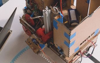
From the image above you can see we still used the rack and pinion design. To keep track of the position of the claw, we used limit switches at the top and bottom of the racks. The 3D printed claw holder would then rotate the claw backwards to drop the plushie once it it the limit switch at the top. Unfortunately due to further complications with the limit switches, using an additional H-Bridge circuits, some uncertainty in the triggering in the limit switches and the lack of replacement motors, we once again axed this design and simplified it further by using servos.
Some other changes were:
-
Using simple servos at the front to hold the bridge. These would then open to drop the bridge exactly like a medieval drawbridge.
-
Significant software refactoring to create classes and functionality for both "small bot" and 'big bot'. We compartmentalized as much of our robot's functionality as possible.
-
The elevator lift was axed in favor of a scissor lift. The issue we could envision with the elevator lift was that it would not allow it to drop downwards without manual reset. The scissor lift, controlled by the same H-bridge design, allowed use to lift and lower the basket so that it could hook onto the zipline.
-
Use of a ball caster rather than a "desk chair wheel" caster that gave us more precision for reversing.
Performance
This has been a long post and it's about time to wrap it up. Our first performance milestone was at Time Trials, roughly two to three weeks before the actual competition. It was here that we should demonstrate to our instructors how much progress we made over the month or two and to set realistic goals for the actual competition.
Because it was Time Trials, expectations were quite low, and since we have yet to make all of our components work to make significant progress through the competition surface, we decided to go for one or two plushies and make a bee-line back to start. We tested the day before and due to various complications a few hours before Time Trials, we only managed to bring the first Ewok and back home. Surprisingly we performed pretty well once we got our feedback; some teams did not managed to do so and others simply picked the Ewok up. It was going to be a tough competition indeed.
It is important to note at this time that Time Trials took place in the same room that everyone usually tests their bots in. This made our robot performance predictable. This, unfortunately, was not the case during the actual competition.
The day before the competition, things we looking pretty good. Observing the results from other teams, very few managed to rescue all the plushies, and so we cut our losses and decided to go just for the first three plushies. We managed to pick up the first Ewok, drop the bridge, cross it, pick up the second Ewok, pass the IR detector, navigate through the stormtrooper table, and was aiming to secure the third Ewok before the competition started. The remainder of our testing simply composed of fine-tuning our settings related to timing, Ewok detection, and tape-following threshold values. Just for fun, we tested the detection sequence and it actually managed to detach successfully and pick up the Ewok on the opposing platform.
What we didn't test for, unfortunately, was the resilience of our Ewok detectors (composed of IR proximity sensors) to changes in lighting. The actual room that the competition was hosted in was significantly brighter than our testing room and had windows that allowed the glaring sunlight interfere with our simple sensors. While we did test our robot in the competition room overnight, the students as a whole dimmed the brightness of the room to make it easier on our eyes, which was not the case during the day.
Our actual competition performance was three points. We picked up an Ewok and returned it to the starting position. That was our first run, and we decided to go for broke and attempt for the second and third. On the second run, Order 66 managed to pick up both the first and second Ewoks, but unfortunately was unable to secure the third and return them to the stating position, leaving us with just two points. At one point during one of the the runs the bot fell off the competition surface, but to our luck we caught it and reset our run quickly.
Final Thoughts
If you've been reading this thoroughly, you probably had thoughts of "why didn't you do this instead" or "maybe this would have worked better" and such. My teammates and myself have the exact same thoughts. If we were to attempt the competition again, we would make significant changes to our robot. Our biggest regret is not verifying our initial assumptions (sheet metal is pretty weak) that influenced our design decisions and as we dived deeper into our prototyping and design, it became increasingly difficult and harder to rationalize giving up on efforts and design, not to mention it is very difficult to tell one of my teammates or myself that "oh that thing you've been working on for the past week? Yeah, that won't work anymore".
If I learned any lesson from all this work, is that simpler is better. The scope of our project was not to build a robot that had all the bells and whistles, but one that could work, and could do that well.
The ENPH 253 Robot Competition was one of the most transformative events in my engineering career; I learned many things from that experience. Everything from prototyping skills ranging to materials to control systems, presentation skills and even mediation, it gave me all the tools I need to tackle any large undertaking in the future.